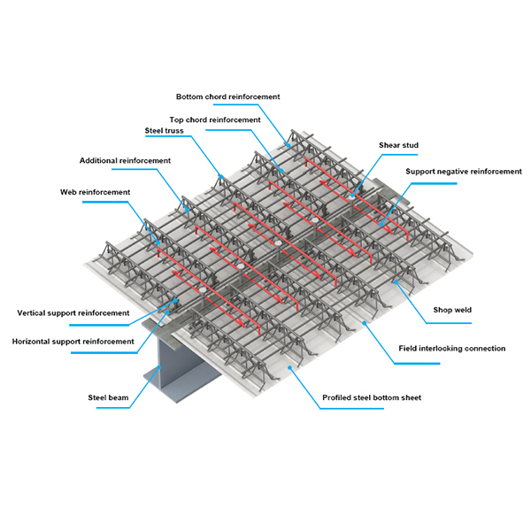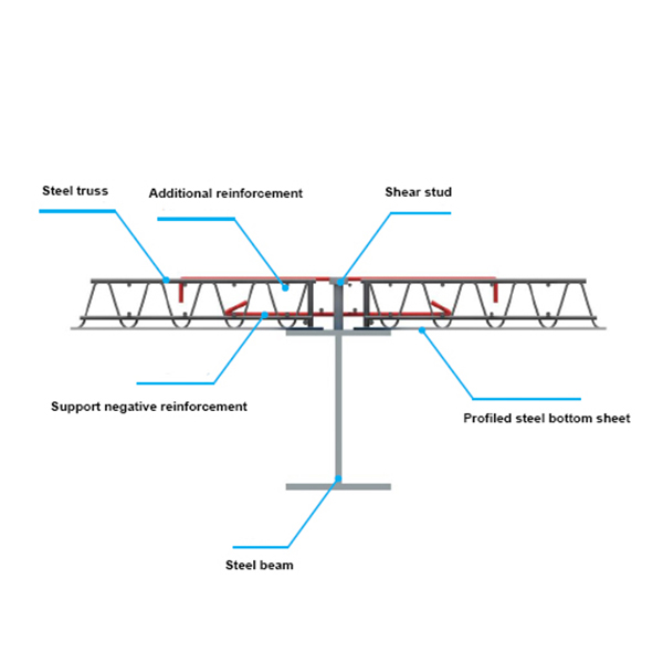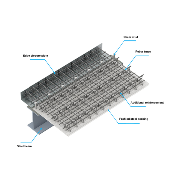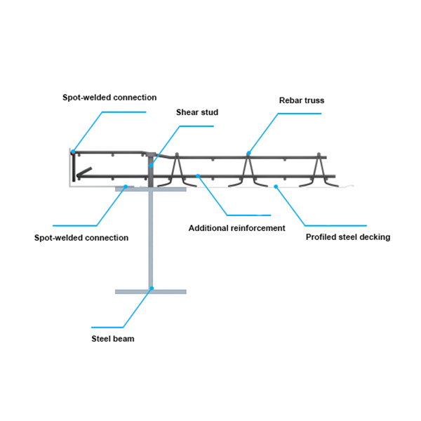
1.1 Lap joint detail over the beam
|
|
|
|
Detail of lap joint over the beam |
Left view |
|
Notes: 1. For profiled steel sheets lapping onto edge beams, the bearing length on steel beams shall be no less than 75 mm, and the bearing length on concrete beams shall be no less than 100 mm. 2. For profiled steel sheets lapping onto intermediate beams, the bearing length on steel beams shall be no less than 50 mm, and the bearing length on concrete beams shall be no less than 75 mm. 3. Profiled steel sheets shall be fixed to steel beams by spot welding, with at least one weld point per trough. When continuous sheets are connected to intermediate supporting steel beams, the number of weld points may be appropriately reduced, provided there are no fewer than two weld points per sheet. 4. The distance from the center of the stud to the edge of the steel beam's top flange or the edge of an embedded part shall be no less than 35 mm; the distance to the edge of the top flange of a concrete beam containing embedded parts shall be no less than 60 mm. |
|
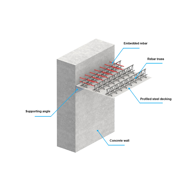
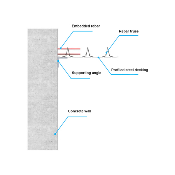
1.2 Connection detail with concrete shear wall
|
|
|
|
Detail of connection with concrete shear wall |
Left view |
|
Notes: 1. Where composite floor slabs are supported against the side faces of shear walls, it is advisable to provide reserved reinforcement in the shear walls for connection to the composite slabs; 2. Expansion bolts shall not be used to secure fixtures to the side faces of shear walls; instead, embedded parts should be reserved and secured by welding; 3. Angle steel specifications shall be no less than L70×5, and the weld leg size shall be no less than 5 mm; 4. Construction sequence: Shear wall reinforcement tying → Embedded part installation → Shear wall concrete casting → Angle steel installation → Floor decking installation → Stud welding → Structural reinforcement tying. |
|
1.3 Cantilever Section Detail
|
|
|
|
Cantilever section detail |
Left view |
|
Notes: 1. When the permanent load during the construction phase is less than 3 kN/m², the thickness of the edge closure plate (Q235) shall be as follows: cantilever length a ≤ 80 mm, plate thickness t = 1.2 mm; 80 < a ≤ 120 mm, t = 1.5 mm; 120 < a ≤ 180 mm, t = 2 mm; 180 < a ≤ 250 mm, t = 2.6 mm; 2. The lap length between the edge closure plate and the top flange of the steel beam shall be no less than 50 mm; intermittent fillet welding shall be used, with a weld length of 25 mm and a spacing of 300 mm; 3. Where the decking ribs meet the beam for edge closure and the profiled steel decking cantilevers, the edge closure plate shall be welded to the profiled steel decking; the weld length shall exceed 25 mm per rib. |
|
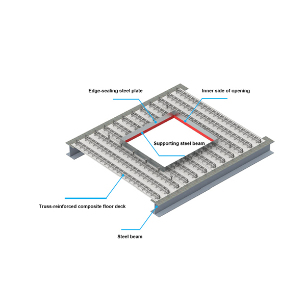
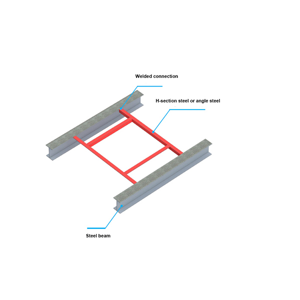
1.4 Opening Detail
|
|
|
|
Opening detail |
Opening detail |
|
Notes: 1. No reinforcement measures are required if the diameter of a circular opening or the side length of a rectangular opening in the composite floor slab is 300 mm or less. 2. Effective reinforcement measures must be taken if the opening size exceeds 300 mm. Connections using channel steel or angle steel may be installed parallel to or perpendicular to the ribs. 3. The spacing of welded studs parallel to the ribs shall not exceed 300 mm; at least one stud shall be welded in each rib trough perpendicular to the ribs. 4. Construction sequence: Layout and marking → Installation of channel steel or angle steel → Installation of galvanized baffle formwork → Laying of floor deck → Stud welding → Civil engineering rebar tying.
|
|
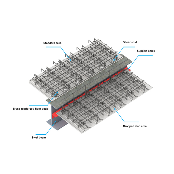
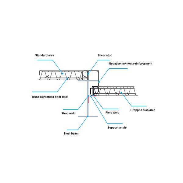
1.5 Dropped Slab Detail
|
|
|
|
Dropped slab detail (enlarged view) |
Left view |
|
Notes: 1. Where one end of the dropped slab is supported against the side of a steel beam, an angle may be welded to the beam web; the angle size shall be no less than L100x6, and the weld leg size shall be no less than 6 mm. 2. Where both ends of the dropped slab are supported against the sides of steel beams, a support plate may be welded to the beam web; the plate shall extend 100 mm beyond the top flange of the steel beam. |
|
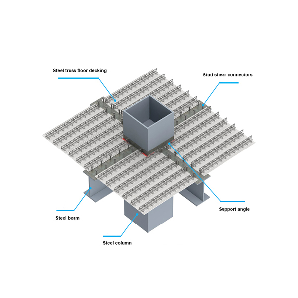
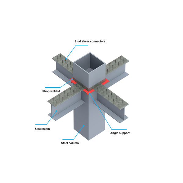
1.6 Column-side support connection
|
|
|
|
Detail of column-side support connection |
Detail of support angle |
|
Notes: 1. Where the composite floor slab is interrupted at the column intersection and the distance from the outer edge of the beam's top flange to the outer face of the column exceeds 75 mm, reinforcement measures must be implemented. 2. Reinforcement may be achieved by welding an angle support to the column or the beam's top flange; the minimum size for the support angle is L50×5. 3. When the column has an open cross-section (e.g., H-section), a horizontal stiffener may be installed on the beam's top flange at the location of the column's open section. 4. Construction sequence: Layout and marking → Installation of support angle → Laying of floor decking → Welding of stud shear connectors → Civil works (rebar tying). |
|
For more information needed or any inquiry,please feel free to contact Yumisteel team.
years of experience



 online service
 +86-592-6095031
 manager@yumisteel.com
 Alina_Yuki
 +8613559086380+8615860744964
 English
 русский
 español
 português
 日本語
日本語